Main Goal:
- Understand the mechanics and dynamics of the Rotary Inverted Pendulum (Furuta Pendulum).
- Design a roadmap to transition from hardware setup to software control using Arduino (low-level) and Python (high-level).
I. What is a Rotary Inverted Pendulum?
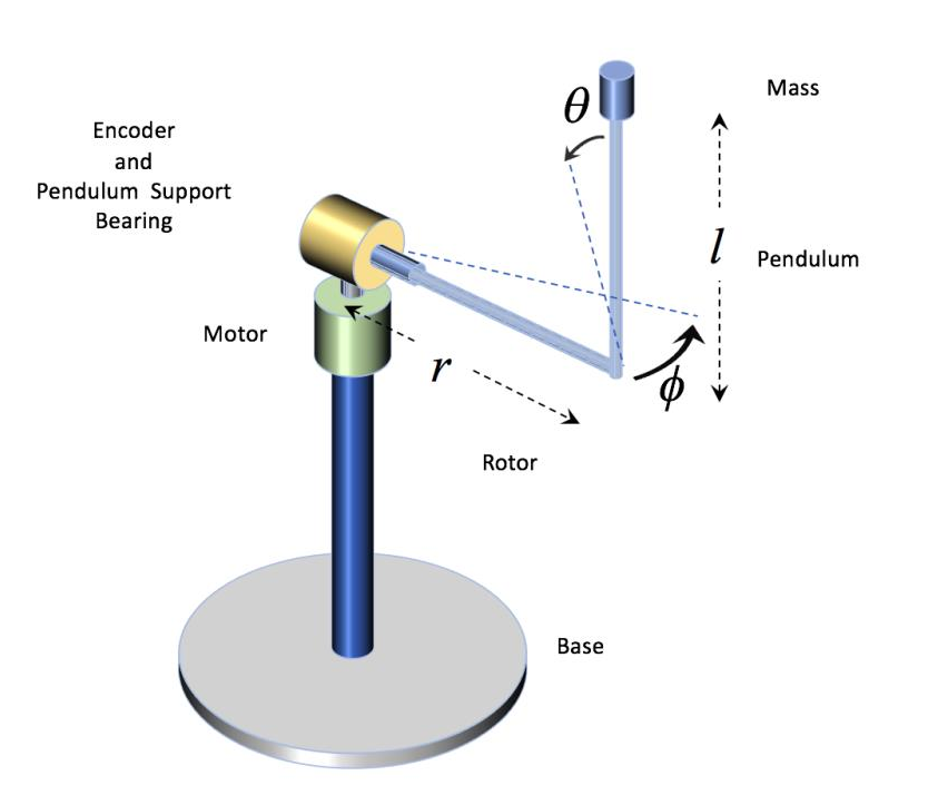
The Rotary Inverted Pendulum consists of a horizontal arm that rotates in the horizontal plane and a vertical pendulum attached to the end of the arm. The goal is to control the motor at the base of the horizontal arm to balance the pendulum in an upright, unstable position.
The Mathematical Challenge
Unlike a standard pendulum, this system is underactuated (one motor for two degrees of freedom) and non-linear. To balance it, we must linearize the system around the upright equilibrium point.
The state vector is typically defined as: \(x = [\theta, \alpha, \dot{\theta}, \dot{\alpha}]^T\) Where:
- $\theta$: Arm angle
- $\alpha$: Pendulum angle
- $\dot{\theta}, \dot{\alpha}$: Angular velocities
II. 12-Week Learning Roadmap
Phase 1: Hardware & Sensing
- Mechanical Assembly: Build or buy the rotary arm and pendulum link. Ensure low friction at the joints.
- Encoder Reading: Use Arduino interrupts to read high-resolution quadrature encoders.
- Goal: Accurately measure $\theta$ and $\alpha$ in degrees/radians.
- Motor Driving: Interface a DC motor with an H-Bridge driver (e.g., L298N or Cytron).
Phase 2: Signal Processing & Communication
- Filtering: Implement a simple Low-Pass Filter or Complementary Filter to clean encoder noise.
- Arduino-Python Bridge: Use
pySerialto stream data from the Arduino to a Python script for real-time plotting. - Visualization: Build a simple 2D dashboard in Python using
MatplotliborPyQtGraphto see the pendulum’s “fall.”
Phase 3: Control Theory Basics
- PID Control: Start with a simple PID loop to control the position of the horizontal arm only.
- The Swing-Up: Create an energy-based controller in Python/Arduino to “swing” the pendulum from the hanging position to the top.
- Balance Control: Implement a PID or LQR (Linear Quadratic Regulator) algorithm to catch and hold the pendulum at the top.
Phase 4: Optimization & Refinement
- Latency Reduction: Optimize the Arduino loop frequency (aim for >200Hz).
- GUI Development: Create a Python interface to tune PID gains ($K_p, K_i, K_d$) in real-time without reflashing the Arduino.
III. The Software Stack
Arduino (Real-Time Control)
The Arduino handles the high-speed tasks: reading encoders and updating the Motor PWM. —
IV. Critical Hardware Checklist
- Microcontroller: Arduino Uno (or ESP32 for faster processing).
- Encoders: 600 PPR (Pulses Per Revolution) or higher for the pendulum joint.
- Motor: High-torque DC motor with minimal backlash.
- Power: 12V-24V external power supply (USB is not enough for motors).
📚 External Resources & References
For a deep dive into the official motor control curriculums and the detailed physics of this system, refer to the following documentation:
- Primary Technical Guide: Introduction to Integrated Rotary Inverted Pendulum (STMicroelectronics)
Happy Building! 🛠️
```